Monday, 14 September 2015

To make or not to - CMake

Its been almost three weeks since I said I would start coding, but with the distraction of the not-quite working motor driver and its replacement I've done little more than a couple of test scripts based on last year's entry. So with a working, if basic, robot up and running its time to turn my attention back to the software.

Most of my Raspberry Pi projects end up being a Python script with a mixture of my own code and the Python example that came with the hardware/tutorial that I've been following. Reasons for this are plentiful, Python tends to be the default language on the Raspberry Pi, it comes pre-installed with a large number of supporting libraries and allows you to get up and running quickly. However its not the language I'm most familiar with, and I'm not convinced its the best use of resources (CPU and RAM) when running on a Model A+.

So for this project I've decided to go with a C++ solution. Its a language that I have some experience of, but I've never done a pure C++ project from scratch, so there's plenty for me to learn here. C++ (and C) is a compiled language, so before you can test any changes you've made the program first needs to be built. With a simple, one file program the compiler can be manually run each time a change is made :-
pi@raspberrypi ~ $ g++ helloworld.cpp
pi@raspberrypi ~ $ ./a.out
Hello world!

Easy enough, but with a multi file project this can quickly get cumbersome, especially when the files have dependencies on each other.
pi@raspberrypi ~ $ g++ helloworld.cpp goodbyeworld.cpp cruelworld.cpp crazyworld.cpp
g++: error: cruelworld.cpp: No such file or directory

My usual solution to this would be to write a Makefile, specifying all the files I needed to build, how to build them, what options were needed to build them, what I wanted the resulting binary to be called and so on and so forth. i.e. a lot of work! Now back at the turn of the century I spent quite some time reading man pages about make and gmake, putting together a complicated, yet elegant, series of makefiles that would allow the building of a project made of thousands of files for a wide range of target platforms. The system, once in place, worked so well that it only needed the occasional minor tweak and, as not actively required, the original knowledge to build such a system faded into the mists of time.

Now spending a few hours re-reading man pages is all that would be needed to help pull that information back out of the long term storage areas of my memory, but surely there must be an easier way, and the way that I decided to follow was 'CMake'.

CMake describes itself as a cross-platform, open-source build system. One that, for the purposes of this project, will happily write the Makefiles for you and, with a quick 'apt-get install cmake' call is readily available for use on the Raspberry Pi of your choice.

Following along with the tutorial on the website we quickly learn that a CMakeLists.txt file is required to describe what files make up our project, a simple one may look like the following.
project (Test)

add_executable(Test helloworld.cpp)
And then you just need to run CMake and out pops the makefiles
pi@raspberrypi ~$ cmake .
-- The C compiler identification is GNU 4.6.3
-- The CXX compiler identification is GNU 4.6.3
-- Check for working C compiler: /usr/bin/gcc
-- Check for working C compiler: /usr/bin/gcc -- works
-- Detecting C compiler ABI info
-- Detecting C compiler ABI info - done
-- Check for working CXX compiler: /usr/bin/c++
-- Check for working CXX compiler: /usr/bin/c++ -- works
-- Detecting CXX compiler ABI info
-- Detecting CXX compiler ABI info - done
-- Configuring done
-- Generating done
-- Build files have been written to: /home/pi
pi@raspberrypi ~$
CMake itself only needs to be run when you make changes to the CMakeLists.txt file, and from this point on whenever you need to compile your project you can run 'make' in the normal way.
pi@raspberrypi ~$ make
Scanning dependencies of target Test
[100%] Building CXX object CMakeFiles/Test.dir/helloworld.cpp.o
Linking CXX executable Test
[100%] Built target Test
pi@raspberrypi ~$ ./Test
Hello world!
Then when you need to add more files its a simple case of adding them to the CMakeLists.txt file
project (Test)

add_executable(Test helloworld.cpp goodbyeworld.cpp cruelworld.cpp crazyworld.cpp)
Re-running cmake and finally make.
pi@raspberrypi ~$ cmake .
-- Configuring done
-- Generating done
-- Build files have been written to: /home/pi
pi@raspberrypi ~$ make
Scanning dependencies of target Test
[ 25%] Building CXX object CMakeFiles/Test.dir/goodbyeworld.cpp.o
[ 50%] Building CXX object CMakeFiles/Test.dir/cruelworld.cpp.o
[ 75%] Building CXX object CMakeFiles/Test.dir/crazyworld.cpp.o
Linking CXX executable Test
[100%] Built target Test
pi@raspberrypi ~$
and you can see that only the new files need to be built (At least at this point).

Of course this is only a simple demonstration, as you add more files and libraries to the project the CMakeLists.txt file will grow, but in a much simpler way that if you had to edit the Makefile itself. In this last case the 100 byte CMakeLists.txt file generated (amongst other files) a 6836 byte Makefile, saving quite a bit of typing.

With the build system sorted I just now need to write some code for it to build!

Leo

Tuesday, 8 September 2015

Introducing - The Mark 2

With a fully working motor driver now in my possession I decided to take this time to update and revise the chassis for my robot based on my experiences with it so far. Having dropped support for my large all-terrain wheels I've been able to increase the width of the chassis and, for now, I've decided to drop the little side tabs as well, mostly to make it easier to cut!


The Mark 1, as I guess I should call it now, had the battery and motor driver haphazardly mounted on top of the robot with wires everywhere. This isn't very pretty, or safe, and didn't leave any room for adding any sensors for the autonomous challenges. To deal with this problem I perused the selection of project boxes available from my local Maplins and selected one that both the motor driver and battery would fit inside.

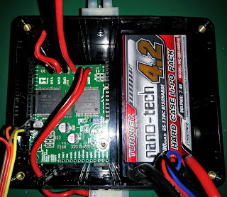
After some trimming and hole drilling the motor driver was mounted inside, with leads coming out of the side to connect up to the motors, and the battery slipped in next to it. As this is an enclosed space its possible that the heat from the motor driver will build up inside it, but for now I'm leaving it as is and will keep an eye on the temperature. If needed I can always add some ventilation and a fan.


The project box itself has a removable lid that is held in place by four screws which,  with the lid removed, make excellent mounting points. Four quick holes drilled in the chassis and the project box is bolted to the underside of the robot. It fits in nicely between the motors, but does reduces the ground clearance of the robot which may cause problems for the obstacle course.


The finishing touches involved cutting a hole in the side to access the Arduino's USB port, for ease  of reprogramming, and cutting another hole in the chassis to pass through the power and I2C  connection to the Raspberry Pi. I also decided to switch over to my smaller wheels, mostly to check nothing will end up dragging across the floor.

The Mark 2 feels a lot more solid and robust than the Mark 1 did, with the majority of the robot's top available for installing sensors and any other components that will help in the PiWars challenge. So with some quick changes to the Arduino's source code to support the newer motor driver it was time to go for a test drive.


As I had full control over the motors this time it was a much more successful test run. Compared to my entry from last year Optimus Pi is already much more controllable, due to the lower geared motors and reduced weight, which bodes well for the autonomous challenges this year (I didn't manage to do any of them last time!).

With a working, controllable robot I can now turn my attention back to the software side of things, at least until my next batch of hardware components arrive!

Leo


Monday, 7 September 2015

A whole new - Motor Driver?

In my last blog posting I was having trouble with the original motor driver I'd selected and had decided to order a different one. The new model is the Pololu dual VNH5019 motor driver and I spent this weekend soldering and connecting it up (At least when I  wasn't busy playing with BB-8).

The fully assembled board
This board has a couple of advantages over the previous one, it uses a newer motor driver chip, can handle a wider range of input voltages, has separate break out pins for running the board without an Arduino, passes through the extra SDA/SCL pins on the Arduino, allows the Arduino to be powered from the battery and comes with a software library to make it really easy to use. Best of all when I loaded up the example code both sets of motors can be seen to move forwards and backwards!

As, hopefully, this will be the last motor driver board I solder up for this robot I thought I'd detail how I went about putting it together, in case anyone else finds it useful reading.

First I took all the components I was planning on soldering to the board and checked that they fitted correctly (This particular board comes with multiple ways of being assembled).


Next I started adding the Arduino shield connectors. First I insert the connector and add solder to one pin,  holding it in place. I then check the position of the connector and, if I'm not happy with it, heat up the solder and adjust the fitting. Its important to get everything lined up correctly, otherwise the shield won't plug into the Arduino. Once I was happy I then proceeded to apply solder to the rest of the pins.


With one connector fixed into place I worked my way around the rest of the board, periodically cleaning and re-tinning my soldering iron to ensure there weren't any build ups of solder, and to try and ensure the new solder melted quickly, as the longer the soldering iron touches the pins, the more heat is transferred into the board, potentially damaging it.

All the shield connectors and jumper connected.
Next was attaching the battery and motor leads. I had already cut these off from the old motor driver and tinned the ends. I was expecting these to go fairly smoothly, but for some reason the solder just didn't want to co-operate, refusing to stick to the board or the wires.. just blobbing up on the end of the soldering iron. Even using a flux pen didn't seem to help much.After a little perseverance I got the wires connected, but without the nice smooth looking solder connection I had managed on the previous board.

Looks a little messy,  but does the job.
The way this shield sits on top of the Arduino means that the motor/battery connections are dangerously close to the ICSP pins. So, to reduce the chance of contact if the robot went over any bumps, I used a glue gun to cover the exposed connectors.

Then it was a case of plugging it into the Arduino and checking that everything was working correctly. I did run into a problem with one of the jumper pins not being connected correctly, but a quick re-heat with the soldering iron got it sorted.

Next job is to install this motor driver onto my robot, but not in the hap-hazarded way I did last time to test it worked, but in a more permanent way.

Leo